
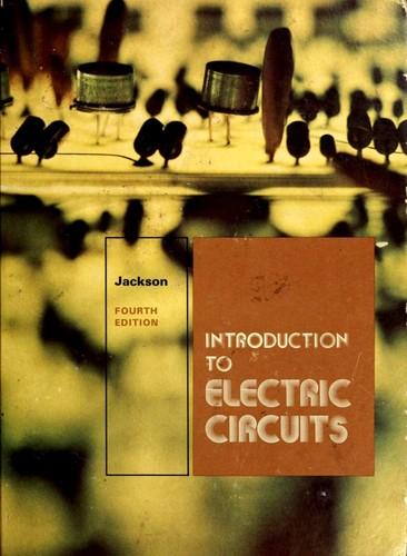
Core Idea
- Difficulty
- Medium
- Read it if
- you are a student or hobbyist looking for a classic, thorough introduction to the fundamentals of electric circuits from a foundational perspective, especially if you appreciate a methodical and detailed approach to learning circuit theory.
- Skip it if
- you are looking for a modern textbook with contemporary circuit design techniques, advanced digital electronics, or extensive use of simulation software, or if you prefer a very concise and fast-paced overview.
Key Takeaways from Introduction to electric circuits
Ohm's Law: The Foundational Relationship
Understanding the interplay of voltage, current, and resistance is paramount to circuit analysis.
Jackson introduces Ohm's Law (V=IR) as the basis of electrical engineering. This relationship, from Georg Ohm, explains how voltage, current, and resistance work together in a circuit. The book shows how to calculate an unknown value when the other two are known. For example, if a 12V battery connects to a 4Ω resistor, the current will be 3A. This law is key to designing and fixing even complex electronic systems, so understanding it is essential for engineers. Its lasting relevance, despite the book's age, shows it is a core principle.
“The current in a circuit is directly proportional to the applied voltage and inversely proportional to the resistance.”
In the book: Chapter 2, 'Ohm's Law and Power', provides numerous example problems illustrating the application of V=IR in various circuit configurations.
Try this: When designing a circuit, use Ohm's Law to select appropriate resistor values to limit current or drop voltage across specific components, ensuring they operate within their safe parameters.
Related ideas: ohms-law, voltage, current, resistance
Series and Parallel Connections
Circuit components behave distinctly when connected in series versus in parallel, impacting overall resistance and current distribution.
Jackson focuses on the difference between series and parallel circuit setups, which is important for circuit design. In series, components connect end-to-end; the same current flows through each, and the voltage drops across them add up to the total. Old Christmas lights are an example: if one bulb fails, the whole string goes out. In parallel, components connect across the same two points, so they all get the same voltage, and the total current splits among them. This is common in house wiring, where appliances work independently. Knowing these differences helps with calculating resistance, current, and voltage, which are vital for fixing and changing circuits.
“In a series circuit, the total resistance is the sum of individual resistances, and the current is the same through all components. In a parallel circuit, the reciprocal of the total resistance is the sum of the reciprocals of individual resistances, and the voltage is the same across all components.”
In the book: Chapters 3 and 4, 'Series Circuits' and 'Parallel Circuits', provide detailed derivations and multiple numerical examples for calculating equivalent resistances and currents in both configurations.
Try this: When designing a system with multiple loads, decide between series (e.g., for voltage division) or parallel (e.g., for independent operation and maintaining constant voltage) based on the specific requirements of the components.
Related ideas: series-circuit, parallel-circuit, equivalent-resistance, current-division, voltage-division
Kirchhoff's Laws: Beyond Simple Circuits
These laws provide powerful tools for analyzing complex circuits with multiple loops and junctions.
While Ohm's Law is basic, Jackson presents Kirchhoff's Current Law (KCL) and Kirchhoff's Voltage Law (KVL) as tools for circuits too complex for simple series/parallel methods. KCL, also called the junction rule, is about charge conservation: the current entering a junction must equal the current leaving it. KVL, or the loop rule, is about energy conservation: the sum of voltage changes around any closed loop in a circuit must be zero. The book shows how to use these laws to set up equations, finding unknown currents and voltages in complex networks. This is the book's best way to move past simple circuits, offering a structured way to solve problems.
“Kirchhoff's Current Law states that the algebraic sum of currents entering a junction is zero. Kirchhoff's Voltage Law states that the algebraic sum of voltage drops around any closed loop is zero.”
In the book: Chapter 5, 'Kirchhoff's Laws', meticulously walks through the application of KCL and KVL to solve multi-loop circuits, including examples with multiple voltage sources.
Try this: For complex circuits with multiple power sources or interconnected branches, apply Kirchhoff's Laws to derive a system of equations that can be solved to find all unknown currents and voltages.
Related ideas: kirchhoffs-current-law, kirchhoffs-voltage-law, circuit-analysis, network-theory
The Concept of Electrical Power
Power represents the rate at which energy is transferred or dissipated in a circuit, crucial for component selection.
Jackson clearly defines electrical power (P) and its link to voltage (V) and current (I) as P = VI. He also shows other forms using Ohm's Law: P = I²R and P = V²/R. This idea is vital for understanding energy use and for choosing components. Resistors, for instance, have a power rating that limits how much heat they can safely handle. Going over this rating breaks the component. The book uses examples like finding the power a light bulb uses or the power a heating element dissipates. This practical focus on power is a key takeaway, connecting theory to real design limits, ensuring engineers pick components that can handle the expected energy.
“Electrical power is the product of voltage and current (P = VI). It represents the rate at which electrical energy is converted into other forms, such as heat or light.”
In the book: Chapter 2, 'Ohm's Law and Power', details the derivations of the power formulas and includes examples calculating power dissipation in various resistive loads.
Try this: When selecting resistors or other components, always calculate the expected power dissipation using P=I²R or P=V²/R and choose components with a power rating significantly higher than the calculated value to ensure reliability and prevent overheating.
Related ideas: electrical-power, energy-dissipation, power-rating, joule-heating
Capacitance and Inductance: Energy Storage
Capacitors and inductors are fundamental components that store energy in electric and magnetic fields, respectively.
Jackson introduces capacitors and inductors as the two main passive parts that store energy, unlike resistors which only use it. A capacitor, two plates separated by an insulator, stores energy in an electric field and has capacitance (C). It resists sudden voltage changes. An inductor, usually a wire coil, stores energy in a magnetic field and has inductance (L). It resists sudden current changes. The book explains how they charge and discharge over time, causing exponential responses in DC circuits. This understanding is basic for AC circuit analysis and filtering, showing how these parts add time-based changes to circuits. The book's clear, early introduction to these ideas is good for a full understanding.
“A capacitor stores energy in an electric field and opposes changes in voltage. An inductor stores energy in a magnetic field and opposes changes in current.”
In the book: Chapters 6 and 7, 'Capacitance' and 'Inductance', explain the physical construction, equivalent circuits, and transient responses (charging/discharging) of these components.
Try this: Use capacitors for filtering out unwanted AC ripples from DC power supplies or for timing circuits. Use inductors in resonant circuits or to block high-frequency signals while allowing DC to pass.
Related ideas: capacitance, inductance, electric-field, magnetic-field, energy-storage, transient-response
AC Circuit Fundamentals: Sinusoidal Excitation
Alternating current introduces phase relationships and new concepts like impedance, crucial for modern electronics.
While the first part of the book covers DC circuits, Jackson moves to alternating current (AC) with a focus on sine waves. This is an important shift, as most generated power and many electronic signals are AC. The book explains concepts like frequency, period, peak value, and RMS value for AC signals. It introduces the idea that in AC circuits, capacitors and inductors do not act as simple open or short circuits but have reactance (X_C and X_L), which depends on frequency. This leads to impedance (Z), the overall resistance for AC circuits, which includes both resistance and reactance. The introduction of phase angles between voltage and current is a major new concept that the book covers systematically, preparing the reader for more advanced AC analysis.
“In AC circuits, voltages and currents vary sinusoidally with time, and the phase relationship between them becomes a critical factor.”
In the book: Chapter 8, 'Alternating Current', defines AC waveforms, RMS values, and introduces the concept of reactance for capacitors and inductors.
Try this: When working with AC signals, account for the frequency-dependent reactance of capacitors and inductors, and use impedance calculations to determine current and voltage relationships, especially for filtering or power factor correction.
Related ideas: alternating-current, sinusoidal-waveform, reactance, impedance, phase-angle, rms-value
Resonance: The Heart of Tuning
Resonant circuits exhibit unique frequency responses, enabling selective signal amplification or rejection.
Jackson introduces resonance in RLC circuits (circuits with resistors, inductors, and capacitors). This is an important idea for understanding how radios tune or how filters work. At the resonant frequency (f_r), inductive reactance (X_L) exactly cancels capacitive reactance (X_C). In a series RLC circuit, this means the lowest impedance and highest current. In a parallel RLC circuit, it means the highest impedance and lowest current (ideally). The book explains how to find the resonant frequency and talks about the 'Q factor,' which shows how sharp the resonance peak is. This explanation simplifies some aspects, as real components have losses, but it gives a solid theoretical base for understanding frequency-selective circuits.
“Resonance occurs in a circuit when the inductive reactance equals the capacitive reactance, resulting in a minimum or maximum impedance at a specific frequency.”
In the book: Chapter 9, 'Resonance', details the conditions for resonance in series and parallel RLC circuits, including formulas for resonant frequency and Q factor.
Try this: Design resonant circuits for specific applications like radio receivers (tuning to a station), filters (passing or blocking certain frequencies), or oscillators (generating specific frequencies).
Related ideas: resonance, rlc-circuit, resonant-frequency, q-factor, frequency-selection
DC Circuit Measurement Techniques
Accurate measurement of voltage, current, and resistance is essential for circuit verification and troubleshooting.
Beyond theory, Jackson includes practical measurement methods, which is very helpful for a basic text. He explains how to use common test equipment like voltmeters, ammeters, and ohmmeters. The key difference is how each tool interacts with the circuit: voltmeters, with high internal resistance, connect in parallel to avoid changing the circuit's voltage; ammeters, with very low internal resistance, connect in series to measure current without a big voltage drop. Ohmmeters, for measuring resistance, need the component to be separate and the circuit off to prevent damage or wrong readings. This practical advice is a strong point, connecting theory to hands-on work and preventing common beginner mistakes.
“Voltmeters are connected in parallel to measure potential difference, while ammeters are connected in series to measure current. Ohmmeters measure resistance with the circuit de-energized.”
In the book: Chapter 10, 'Electrical Measurements', covers the principles of operation and correct connection methods for various meters, including potential pitfalls.
Try this: Always connect a voltmeter in parallel across the component you wish to measure. Connect an ammeter in series by breaking the circuit path. Always de-energize the circuit before measuring resistance with an ohmmeter.
Related ideas: voltmeter, ammeter, ohmmeter, circuit-measurement, troubleshooting
The Importance of Circuit Diagrams
Standardized symbols and clear diagrams are the universal language of electrical engineering, enabling effective communication.
Jackson constantly highlights the importance of circuit diagrams. From the start, he introduces standard symbols for parts like resistors, batteries, switches, and grounds. Using these symbols throughout the book shows their importance as the common language of electrical engineering. A well-drawn circuit diagram is not just a picture; it is a precise plan that tells anyone with the right knowledge how a circuit works and connects. The book shows how to turn physical circuits into diagrams and vice versa, stressing clarity and following rules. This focus on clear communication through standard diagrams is a basic skill often missed in purely theoretical books, making it a key practical lesson.
“A circuit diagram is a pictorial representation of an electrical circuit, using standardized symbols to denote components and their connections.”
In the book: Throughout the book, every example and problem is accompanied by a clear, correctly drawn circuit diagram using standard symbols, reinforcing their importance.
Try this: Always draw clear, standardized circuit diagrams before building or analyzing a circuit. This aids in design, debugging, and communication with other engineers.
Related ideas: circuit-diagram, schematic-symbols, electrical-notation, technical-communication
Problem-Solving Methodology
A systematic approach to circuit analysis is more effective than trial and error.
While not a separate chapter, a running theme in Jackson's book is the importance of a structured way to solve problems. For each new idea, he follows a pattern: define the principle, give formulas, go through example problems step-by-step, and often add practical points. This method encourages readers to first identify what they know and don't know, draw or read a clear circuit diagram, pick and use the right laws (Ohm's, Kirchhoff's, etc.), do calculations, and check if the results make sense. This careful method, instead of random guessing, is essential for learning circuit analysis and building good engineering judgment. It is the overall lesson of the book: how to think like an electrical engineer.
“Successful circuit analysis often relies on a methodical approach: understand the problem, draw a clear diagram, apply relevant laws, and verify the results.”
In the book: Every chapter consistently presents problems with a clear 'Given', 'Find', and 'Solution' structure, guiding the reader through the analytical process.
Try this: When faced with any circuit problem, adopt a systematic approach: draw the circuit, label all knowns, identify unknowns, choose the appropriate analytical tools (Ohm's Law, KCL, KVL), solve the equations, and double-check your answer.
Related ideas: problem-solving, analytical-skills, engineering-methodology, critical-thinking
Introduction to electric circuits Quotes
“The fundamental principles of electric circuits are essential for understanding more complex electrical and electronic systems.”
“Ohm's Law, V = IR, is the cornerstone of DC circuit analysis.”
“Kirchhoff's Current Law states that the algebraic sum of currents entering a node is zero.”
“Kirchhoff's Voltage Law states that the algebraic sum of voltages around any closed loop is zero.”
“Series circuits have a single path for current to flow.”
“In a series circuit, the same current flows through all components.”
“Parallel circuits provide multiple paths for current to flow.”
“In a parallel circuit, the voltage across all branches is the same.”
“Resistors in series add directly: R_total = R1 + R2 + ...”
“Resistors in parallel have a reciprocal relationship for total resistance: 1/R_total = 1/R1 + 1/R2 + ...”
“Capacitors store electrical energy in an electric field.”
“Inductors store energy in a magnetic field and oppose changes in current.”
“AC circuits involve time-varying voltages and currents, often sinusoidal.”
“Impedance is the total opposition to current flow in AC circuits, encompassing resistance and reactance.”
Quiz
10 questions on the main ideas. Each answer comes with a short explanation.
Question 1
What is Ohm's Law?
- V = I / R
- V = I * R
- V = R / I
- V = I + R
Show answer
B. V = I * R Ohm's Law states that the voltage (V) across a resistor is directly proportional to the current (I) flowing through it and the resistance (R) of the resistor. Mathematically, it is expressed as V = I * R.
Question 2
What is the unit of electric current?
- Volt
- Ohm
- Ampere
- Watt
Show answer
C. Ampere The standard unit of electric current is the Ampere (A), named after André-Marie Ampère. It represents the rate of flow of electric charge.
Question 3
Which of the following is a passive component in an electric circuit?
- Transistor
- Operational Amplifier
- Resistor
- Diode
Show answer
C. Resistor Passive components, such as resistors, capacitors, and inductors, do not require an external power source to operate and cannot amplify or generate power. Active components, like transistors and op-amps, require a power source and can amplify signals.
Question 4
Kirchhoff's Current Law (KCL) deals with the conservation of:
- Voltage
- Charge
- Energy
- Power
Show answer
B. Charge Kirchhoff's Current Law states that the algebraic sum of currents entering a node (or junction) is equal to the algebraic sum of currents leaving that node. This is a direct consequence of the conservation of electric charge.
Question 5
What is the equivalent resistance of two 10-ohm resistors connected in parallel?
- 20 ohms
- 10 ohms
- 5 ohms
- 0 ohms
Show answer
C. 5 ohms For resistors in parallel, the equivalent resistance (R_eq) is calculated using the formula: 1/R_eq = 1/R1 + 1/R2. In this case, 1/R_eq = 1/10 + 1/10 = 2/10. Therefore, R_eq = 10/2 = 5 ohms.
Question 6
What does the term 'capacitance' measure?
- The opposition to the flow of alternating current
- The ability to store electrical energy in an electric field
- The rate at which electrical energy is converted into heat
- The ability to store magnetic energy in a magnetic field
Show answer
B. The ability to store electrical energy in an electric field Capacitance is the property of a component (a capacitor) to store electrical energy in an electric field. It is defined as the ratio of the change in electric charge to the corresponding change in electric potential.
Question 7
In a series circuit, the current is:
- Different through each component
- The same through each component
- Zero if one component fails
- Dependent on the resistance of each component
Show answer
B. The same through each component In a series circuit, there is only one path for the current to flow. Therefore, the current is the same through every component in the circuit.
Question 8
What is the unit of power in an electrical circuit?
- Joule
- Volt-Ampere
- Watt
- Farad
Show answer
C. Watt The unit of electrical power is the Watt (W), which is defined as one joule per second. It is also equivalent to the product of voltage (Volts) and current (Amperes), hence Volt-Ampere.
Question 9
Which theorem allows us to simplify a complex network of resistors, voltage sources, and current sources into an equivalent circuit with a single voltage source and a single series resistor?
- Kirchhoff's Voltage Law
- Superposition Theorem
- Thevenin's Theorem
- Norton's Theorem
Show answer
C. Thevenin's Theorem Thevenin's Theorem states that any linear electrical network can be replaced by an equivalent circuit consisting of a single voltage source (V_th) in series with a single resistor (R_th). Norton's Theorem is similar but uses a current source in parallel with a resistor.
Question 10
What is the impedance of a series RLC circuit at resonance?
- Zero
- Infinity
- Equal to the resistance
- Equal to the inductive reactance
Show answer
C. Equal to the resistance At resonance in a series RLC circuit, the inductive reactance (XL) equals the capacitive reactance (XC). Since impedance (Z) = R + j(XL - XC), at resonance, XL - XC = 0, making the impedance equal to the resistance (R).
Introduction to electric circuits FAQ
What are the fundamental concepts covered in 'Introduction to Electric Circuits' by Jackson?
The book covers essential concepts such as Ohm's Law, Kirchhoff's Laws, series and parallel circuits, voltage, current, resistance, and power. It also delves into basic circuit analysis techniques.
Is 'Introduction to Electric Circuits' suitable for beginners with no prior knowledge of electronics?
Yes, the book is designed as an introductory text. It assumes little to no prior knowledge and builds concepts gradually, making it accessible for students and enthusiasts starting their journey in electrical engineering.
What are some practical applications discussed in Jackson's electric circuits book?
The book often includes examples and problems related to practical applications like simple electronic devices, household wiring, and basic power distribution systems, helping readers see how theory translates to real-world scenarios.
How does 'Introduction to Electric Circuits' compare to other introductory circuit analysis textbooks?
Jackson's book is known for its clear explanations and step-by-step problem-solving approach. It strikes a good balance between theoretical rigor and practical relevance, often praised for its readability.
What types of circuit analysis methods are taught in this book?
Readers will learn fundamental analysis methods including nodal analysis, mesh analysis, superposition, and the use of Thévenin and Norton equivalents to simplify complex circuits.
Does the book cover AC circuits or only DC circuits?
Typically, an introductory book like this will cover both DC (Direct Current) and AC (Alternating Current) circuits. It will introduce concepts like impedance, reactance, and phasors for AC analysis.
Are there practice problems and solutions available in 'Introduction to Electric Circuits'?
Most editions of this textbook include numerous end-of-chapter problems to reinforce learning. Some may also provide answers to selected problems or a companion solutions manual.
What prerequisites are recommended before starting this book?
While designed for beginners, a basic understanding of algebra and physics, particularly mechanics and electromagnetism, can be beneficial. Calculus is often introduced later for more advanced topics.
Is this book suitable for an undergraduate electrical engineering course?
Yes, 'Introduction to Electric Circuits' by Herbert W. Jackson is commonly used as a primary textbook in first or second-year undergraduate electrical engineering and technology programs.
What is the importance of understanding circuit analysis for aspiring engineers?
Circuit analysis is a foundational skill for electrical, computer, and many other engineering disciplines. It's crucial for designing, analyzing, and troubleshooting electronic systems and devices.
Enjoyed the summary?
A summary gives you the shape of the book. The book itself has the detail, the examples and the voice.
Find Introduction to electric circuits on AmazonAs an Amazon Associate, BookBrief earns from qualifying purchases. How we're funded